

In Part 4 I discussed dynamic balancing theory, including an explanation of the terms used to describe the tolerances suitable for a typical high performance engine. The previous post finished off with the crankshaft (complete with crank gears) balanced well within the target tolerance of 4gram-25mm. This article covers the remainder of the reciprocating assembly i.e the flywheel, clutch pressure plate and crankshaft pulley.
Flywheel
Before balancing the flywheel, it’s important to check it runs true when bolted to the crank. Any significant amount of run-out will result in huge unbalance. I’ve seen some crank/flywheel combinations with run-out in excess of 1.5mm (.060″). In this instance it was less than .002″.

measuring flywheel runout with a dial indicator running on the pressure plate mounting face
Time to subject the flywheel to its first spin. The figures below show the dramatic change in unbalance that took place when bolting the unbalanced flywheel on to the balanced crank. Top row figures of 1.84 & 0.77 grams are for the crank on its own – the lower figures (13.1 & 57.9 grams) are for the crank and flywheel together:

The effect of adding an unbalanced flywheel to a balanced crank
Because the flywheel has a much larger diameter than the crank, it has the potential to throw things way off track . As explained in Part 4, the bigger the correction radius, the greater the effect of any unbalance. Notice how unbalance at the pulley end of the crankshaft has also increased, illustrating how a large amount of unbalance tries to pull the crankshaft away from its axis of rotation.
Knowing the crankshaft has already been balanced, we know the flywheel is responsible for any new unbalance. Therefore corrective work should be confined to the flywheel only. Although that 57.9 gram figure looks daunting, remember it’s referring to unbalance at a 25mm radius, whereas the outer edge of the flywheel where I’ll be removing weight is approx 115mm from the centre of the crank, multiplying each gram I remove by a factor of more than four. Here’s the flywheel in the process of being drilled to remove the required weight:

Removing weight from the flywheel to reduce unbalance
It took three closely spaced 9.5mm diameter ‘dimples’ to arrive at the following crank and flywheel balance tolerance:
Both ends of the crank are now under the target tolerance of 4grams-25mm
Clutch pressure plate
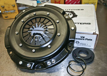
KEP Stage 1 pressure plate, with supplied thrust pad removed to suit late style clutch release bearing
Next step is to bolt on the clutch pressure plate. For Project 2110 this will be a Kennedy Engineering Products Stage 1. It’s vital the pressure plate is a very snug fit in the flywheels recess. Fortunately KEP plates are generally very good in this respect. When removing and replacing the pressure plate, it’s essential it goes back in the exact same position each time. If it’s a sloppy fit in the flywheel register, any slight deviation from the position in which it was balanced will result in a significant increase in unbalance due to it’s relatively large diameter. If your pressure plate is anything other than a very snug fit inside the flywheel, correct the problem before having it balanced.
Once the pressure plate has been balanced, it’s marked to ensure it always goes back in the same position. In the photo below, the clutch, flywheel and even the clutch bolts are engraved so the owner can reassemble the parts to exactly replicate things as they were when they were balanced:

Matching the numbers ensures the pressure plate is bolted in the correct balanced position
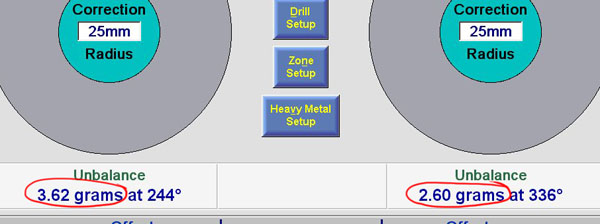
Based on previous experience, it’s not uncommon to see a KEP pressure plate push a balanced crank and flywheel combination a long way out of tolerance, despite the fact KEP claim their pressure plates are balanced at the factory. In reality, this particular pressure plate was reasonably good – not within our tolerance but not so far out to be a major problem.

Initial spin with KEP Stage 1 pressure plate
This was an easy fix – taking a single dimple on the outer edge of the pressure plate to bring the tolerance withing target. The final figures for left and right planes were: 2.01 grams and 1.05 grams respectively (I forgot to nab a screenshot of the final spin).
Crankshaft pulley
The final step – balancing the crankshaft pulley. Project 2110 is being fitted with a stock diameter billet steel crankshaft pulley. Because it’s smaller in diameter, any unbalance is likely to be less significant than seen when fitting larger items, like the pressure plate and flywheel.
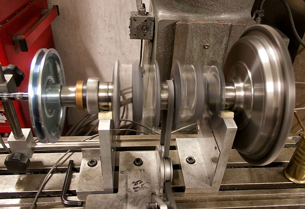
Crankshaft pulley is the last item added to the reciprocating assembly
Results from that first spin with the crank pulley:
First spin with crank pulley
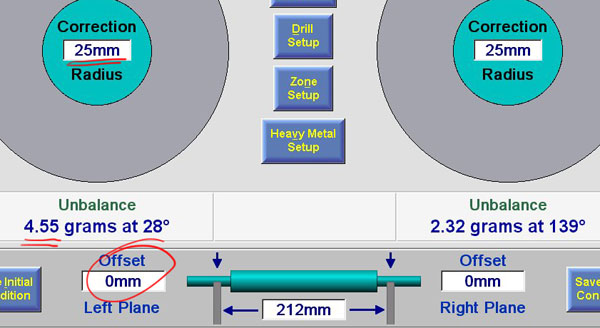
A quick explanation of how the dynamic plane offset feature of the Turner Technology crank balancer makes light work of isolating unbalance… notice in the screenshot above how I’ve set the ‘Correction Radius‘ set to 25mm and ‘Offset’ to 0mm, i.e. we have a tolerance of 4.55 grams-25mm on the left plane. Because I’m balancing the crank pulley, any weight removal will be at a greater radius than 25mm. Also, the pulley is some distance from the left upright (no3 main bearing journal). By entering the distance between the back of the pulley and no3 main journal (offset), along with the radius of the where I’ll be drilling into the pulley, the software automatically recalculates the amount of weight removal based on the new location:
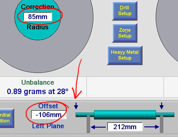
Changing correction radius to 85mm and left plane offset to 106mm to pinpoint the place where material will be removed from the crankshaft pulley, (notice how the left plane arrow has shifted from the left upright).
In other words, removing 0.89 grams from the outer edge of the crankshaft pulley (85mm from its centre), has exactly the same effect as losing 4.55 grams at a distance pf 25mm from the centre of the no3 main bearing journal.
Having drilled the crank pulley as indicated by the software, and resetting correction radius back to 25mm and offset to zero, here’s the final result for Project 2110’s complete crankshaft assembly:

Project 2110’s complete crank assembly: dynamically balanced and ready to go
So why go through this step by step process (balance crank by itself, add flywheel-balance flywheel, add pressure plate-balance flywheel etc etc)? Some places will balance the entire assembly as a unit. It’s certainly a lot quicker to do it that way but when carrying out the work as I’ve described, you know each individual component will work independently as a balanced item. The advantage of this method? When it comes time to replace one of those components (e.g. the clutch pressure plate), I can balance the new pressure plate on a donor balanced crank/flywheel setup and supply the new pressure plate safe in the knowledge it won’t upset overall engine balance. If instead, the reciprocating assembly had been balanced as a completely assembled unit, overall balance may be good but the individual parts by themselves can have large values of unbalance. Adding a newly balanced pressure plate to a crank assembly that was originally balanced as a complete unit will almost certainly make overall unbalance worse than it was before.
Previous Project 2110 posts:
Part 1: Introduction
Part 2: Bore & Stroke
Part 3: Crankcase Preparation
Part 4: Dynamic Balancing (intro and theory)
Sign up to the newsletter for email notification of the the next installment of Project 2110.
Updates are also posted on the JMR facebook page